Large Impeller Balancing Case Study
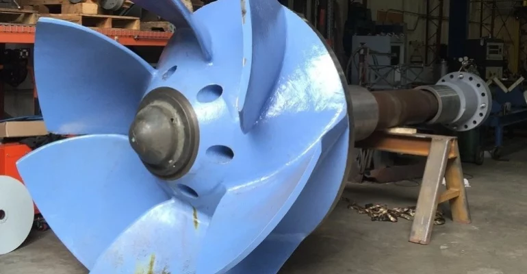
The assembly above is the final installed arrangement. There are two hydrodynamic bearings on the shaft. The balancing tolerances are applied at those locations. There is a coupling at the far end. The pump runs vertically, impeller down. The assembly is 15,000 pounds. These pumps have been balanced multiple times during previous rebuilds.

Balancing Procedure
The customer intended to have us balance two assemblies using the following method:
- Balance the impellers on a separate balancing arbor before assembling them to the pump shaft.
- After balancing on an arbor, the impellers were assembled to the pump shafts and balance was trimmed.
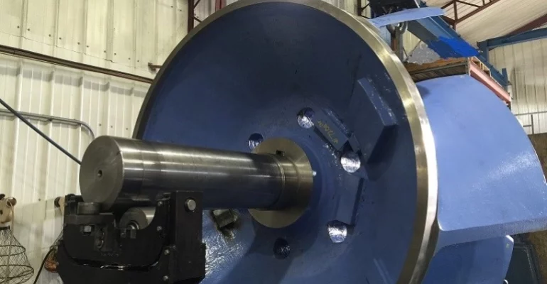
The impeller on the balancing arbor, in the balancer, looks like this:

Multiple balancing weights decorate the top side of the impeller. Inspection of the blades reveals little evidence of material removal on the blades. This is an indication the impeller has not been two plane balanced. Before balancing, the locations where the vibration readings are taken must be identified. In this case these locations are marked by two vertical planes orthogonal to the axis of rotation of the part. The balancing planes were identified as follows:
The top seal ring marked the left plane. The location 8” above the tip of the lowest part of the blade on the right side of the impeller marked the right plane. The planes are therefore separated by 40”, the magnitude of couple or two-plane unbalance. On the blade side, that plane location gives us immediate quantity of material for removal. The idea is to finish balancing knowing the couple, and removing most of the single plane. This allows us to predict the unbalance at the bearing locations before installing the impeller, forever on the shaft. Compromises on the residual unbalance amounts can save time and money. Sometimes exceptions have to be made at this stage as correcting the impeller to super low tolerances can hurt the structural integrity of the blades.
Table 1: Balancing Data for the first impeller on the arbor:
| 7200# Impeller | BEFORE BALANCE | AFTER BALANCE | VECTOR SUM | |||
|---|---|---|---|---|---|---|
| Top | Blade | Top | Blade | Before | After | |
| ON ARBOR | 493 ozin | 1640 ozin | 204 ozin | 211 ozin | 2059 ozin | 88 ozin |
The blade end of the impeller had significant unbalance that was never previously corrected.
Balance tolerance
It is very important to understand what the assembly unbalance requirements are before balancing the components. These unbalance requirements are called the balancing tolerance. The balancing tolerance puts in perspective the scope of work that needs to be done to correct a component
4w/n = ( 4 x 15,000 # ) / 100rpm = 600 ounce inches
The impeller assembly when in service should have less than 300 ounce inches at each bearing centerline.
It is important to note “couple unbalance amount” is the same at any location along an assembly as long as it is measured with the same plane separation spread. Additionally, if it’s distance is doubled between the balancing planes, the residual unbalance would be ½ that of the closer original distance.This concept allows you to potentially reduce the amount of work necessary to correct the rotor.
The spacing between the bearings on the final pump assembly with coupling happened to be right at 80 inches. Therefore as much as 600 ounce inches of unbalance could be left on the impeller in each plane. We chose not to do that as making the correction was easy and the customer was willing to pay to go below this maximum. The residual unbalance after balancing was right at about 200 ounce inches. This is about 1/3 of the absolute maximum. The phase angles have been omitted in the data for simplicity to the customer. Looking at the post-balance data, the vector sum is very low. Most of what remains is pure couple. Theory says there should be about 100 ounce inches when assembled.
Assembly Balancing
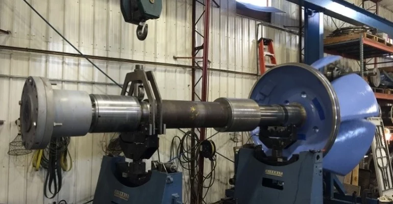
The impeller was assembled with the shaft and coupling. This is what it looks like on the balancing machine. The balancer is a Gisholt Turbine Rotor Balancer. It is a soft bearing machine. HITEK modified this machine so it can be run as an above or below resonance balancer. It allows us to balance the very tight tolerances at very low speeds. This assembly was balanced at 100 rpm. It is instrumented with an IRD 236 which is capable of as low as 60 rpm. Most hard bearing machines require as much as 200 rpm minimum. This allows for much safer handling of the components and much lower drive horsepower requirements. The spin up and slow down duration is also reduced. The balancer is equipped with HI-TEK’s own exclusive self-aligning roller bearing blocks. This allows for virtually no thrusting problems and prevents damage to the shaft from the roller contact.

We were not able to rest on the hydrodynamic bearings. They can’t be fed fluids in the balancer. Clean smooth diameters on the shaft were used to run rollers. Not running on the actual bearings helped with weight distribution and kept the rotor from becoming an overhung mass. An overhead bearing was used as a safety as the coupling end was only a few thousand pounds.
Results
This is the balancing data from the impeller previously balanced on the arbor. The balance tolerance is applied at the center of the bearing location.
| TOP | BOTTOM |
|---|---|
| 52 oz in | 130 oz in |
As you can see no corrections were needed. 4w/n = 4(15000) /100 = 600 oz in
Second Impeller Assembly
The second impeller assembly presented a greater challenge. It turns out the bore in the impeller had been previously modified, and was too big for the arbor. Instead of reworking the arbor, we applied what we learned from the first assembly and chose to forgo balancing the impeller separately.
The assembly was set up in the balancer as per the photo above and as the previous assembly. The data was as follows:
Before balancing at sleeve bearings (this impeller was not balanced on an arbor):
| TOP | BOTTOM |
|---|---|
| 395 oz-in@335 | 2906 oz in@260 |
Two plane at impeller correction planes:
| Seal (top) | Blade (bottom) | Vector Sum |
|---|---|---|
| 5746 ozin | 1940 ozin | 4162 oz in |
After balancing at bearings:
| Top | Bottom | Sum |
|---|---|---|
| 190 oz in | 183 oz in | 123 oz in @279 |
4w/n = 4(15000) / 100rpm = 600 ozin
Corrections made on the impeller blades by grinding, and by welding weights on the top of the impeller.
Reducing unbalance using two planes corrected unbalance at the bearings.
Conclusion:
Knowing what is important can save thousands of dollars in time and prevent damage to parts by incorrectly applying tolerances i.e. doing too much balancing. Having the first impeller-on-arbor and then being able to measure the result was helpful in our approach to this second assembly. We knew we needed to balance the second assembly on the pump shaft before we completed the first assembly. We tested balancers response of the overhung rotor on the first assembly. We knew we were on a path to success as we were able to use the first assembly as a test “calibration rotor”. We understood that we needed to deal with overhung couple and we knew the machines resolution was up to the task. Our custom built slow-speed soft-bearing balancer, operated by our skilled technicians and engineers correctly and efficiently solved this customer’s vibration problems.


