 We recently received a call from a customer who makes fiber optic strands. Fiber optic strands are glass tubes that are heated and stretched into long optic fibers that are later incorporated into a data transmission cable. They hired us to help find the cause of a vibration problem in the fan enclosure used in the production of making the fiber optic strands.
The Job
The main stranding room has a highly controlled atmosphere that is dust filtered, as well as, having the humidity and temperature control highly monitored. On a floor, just above the production room, sits a fabricated steel box enclosure with two 30 hp direct drive fans. The steel box is decent sized. To give you a good visual idea, it is about one-half the size of an overseas shipping container. There is some bracing in the long spans along with ductwork attached to the outside going in and out. The ducting is about 4’ square in cross section.
The Fans
Inside the box are two 30 hp direct drive fans. The fan wheels are about 48” in diameter. The motors sit on a chassis suspended on vibration isolators with the required “more than an inch of static deflection.” The fans sit side-by-side. A series of airflow control devices are employed. There is an adjustable damper just outside the enclosure on the inlet duct. Both fans are speed controlled on variable speed AC drives. There are sophisticated inlet dampers built into each fan inlet. The complaint was that vibration was transmitting from the fans into the walls of the enclosure. During full production, the fan enclosure vibration was enough to concern the facility manager. His concern was vibration would begin to break apart the enclosure. Conversely, it seemed unlikely the fans were the culprit of the destructive vibration, as the isolators seemed to be doing what they were intended to do. The vibration seemed to be at much lower frequency than the fan speed. Finding the cause of vibration requires eliminating sources one at a time.
Steps we took
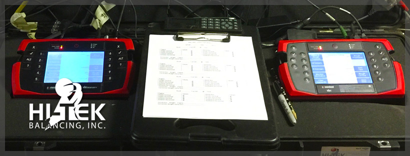
The first step was to check the balance condition of the fan wheels and compare that to industry standards. The fan wheels were backward inclined airfoil plenum type made from aluminum. Each fan wheel was instrumented using a four channel Comtest Vibration analyzer/balancer. Two plane balancing runs were executed. The balance condition on both fans was 5x better than that the industry standard of 0.1 inches per second, thus eliminating unbalance as a source of vibration.
Airflow Induced Vibration
Our attention turned to the ducting, the dampers, and the static pressure gauges. Unfortunately, we could not recreate the level of vibration experienced during full facility production. Parts of the facility were in holiday shutdown. Other environmental systems were not running. So not having the facility in full production was altering the static pressures in the facility and ducting. We questioned the facility managers about the requirements of the airflow in the production room. No one seemed to really know if there were any particular cfm and static pressures. No one knew that the damper setting was upstream. The internal fan inlet dampers have pneumatic actuators that were disconnected in the wide-open setting. The long straight inlet duct transitioned into a wye through two square cutouts in the enclosure. It appeared there was nothing directing the air toward the cutouts in the wye. The air came down the duct, and slammed into the wall of the enclosure, and had to find its way through the openings of the fans.
Our Conclusion and Recommendation
We have realized this will potentially create a turbulence and flow swapping, causing the enclosure to be exposed to airflow turbulence and pulsations. The cabinet is not very rigid and the static pressures are affecting hundreds of square feet of lightly supported sheet metal. Vibration measurements of the motors showed low frequency pulsations in and around 140 cpm. Smooth flow is imperative and will remain elusive until testing various damper and flow settings can be tested. None of this can take place until there is a full understanding of the requirements. Our conclusion and recommendations are duct modifications may be necessary.
At HI-TEK we are not airflow engineers per se. We are balancing and vibration experts and many times know more about ducting and airflow than we realize. Performing vibration analysis and balancing allows for the many diverse opportunities to see, feel and measure vibration.
We look at all the causes and effects of vibration and balancing analysis. Let us help if you are unsure. Give us a call and let our experts take care of all your balancing and vibration needs.


